Arduino
![]()
This is an interesting option because it allows DUELink to be used in 2 very different ways. You can use a third-party Arduino board to control a chain of Daisylinked DUELink modules. Also, you can program any DUELink module using the Arduino IDE/software Standalone. We will cover them individually.
Daisylink
Any board running Arduino software can utilize DUELink modules. An example can be Arduino Uno R4 WiFi, which already includes a JST connector.
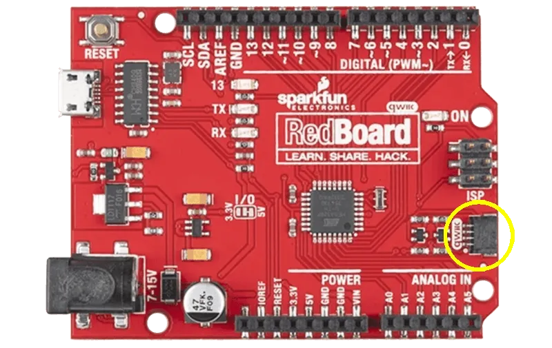
The Sparkfun Redboard Qwiic is another option.
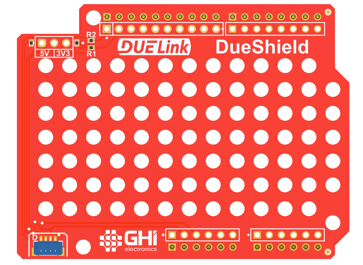
Boards without a JST connector can use DueShield. It has a Downlink connector and an area with hole matrix for mounting DUELink modules.
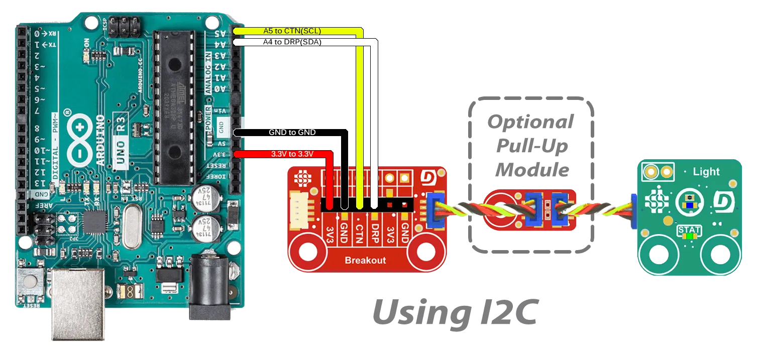
You can also use the Breakout module to wire the connections using either I2C or UART.
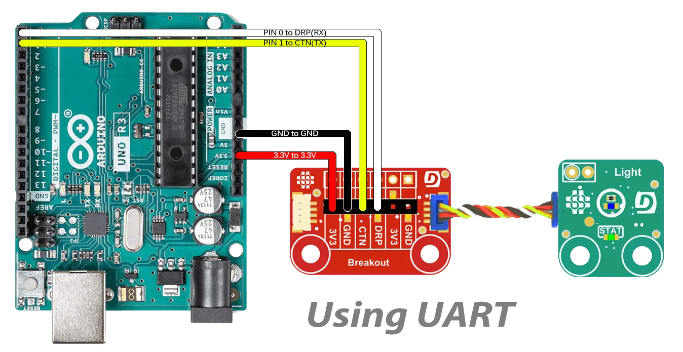
When using I2C, pull-up resistors are required. If your board doesn't have them, we have a PullUp module for you.
To use daisylinked DUELink modules, you need to install the DUELink Arduino library.
Under Tools on the top menu of the Arduino IDE select Manage Libraries.
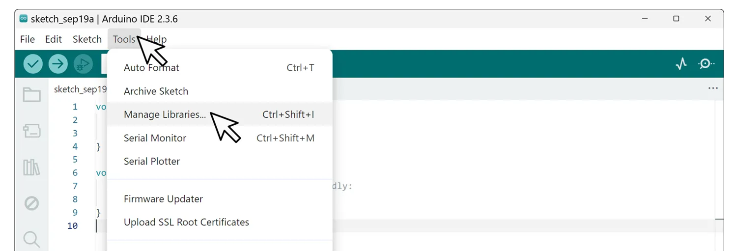
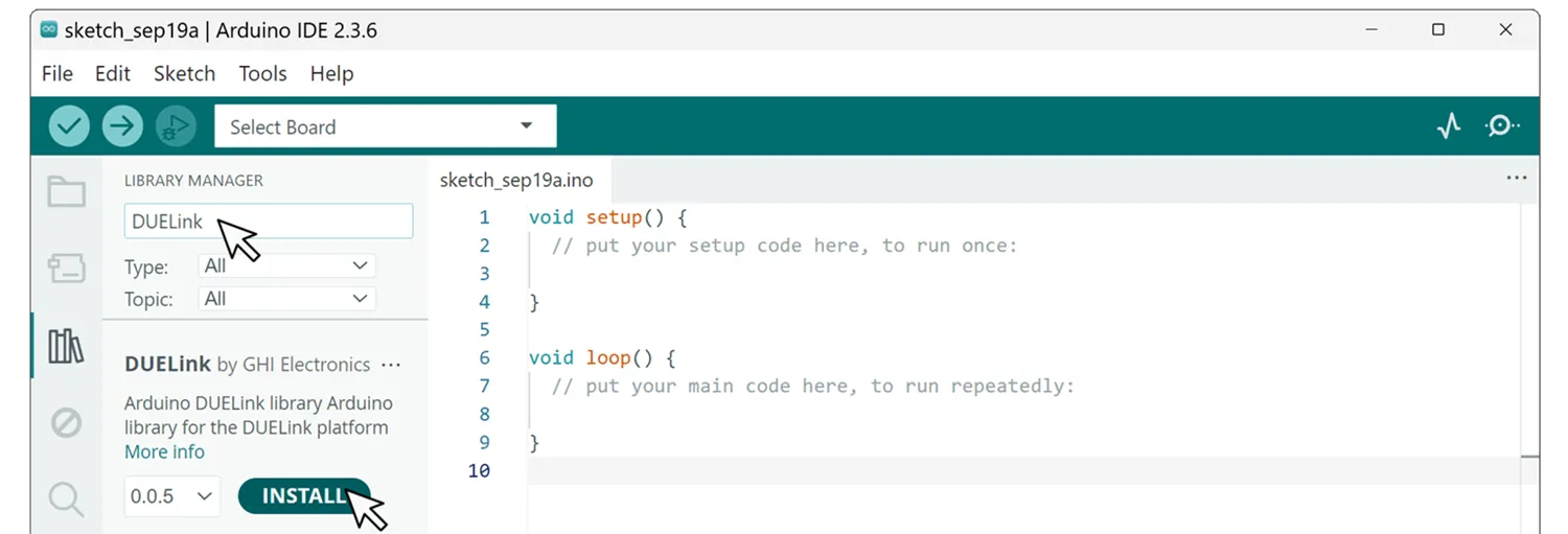
Type DUELink in the search window and then click Install
Now let's connect any 2 DUELink modules to the Downlink port. This example code will blink both STAT LEDs on both modules. Note how the STAT LED of the first module blinks only 10 times while the second module blinks forever.
#include <DUELink.h>

SerialTransport transport(Serial2);
DUELink duelink(transport);

void setup() {
  Serial.begin(9600);
  Serial2.begin(115200);
  duelink.Connect();
  duelink.Engine.Select(1);//Selects the first DUELink Module
  duelink.System.StatLed(200, 200, 10);//Blink STAT 1st module 10x
  duelink.Engine.Select(2);//Selects the second DUELink Module
  duelink.System.StatLed(200, 200, 0);//Blinks STAT 2nd Module forever
}

void loop(){
}
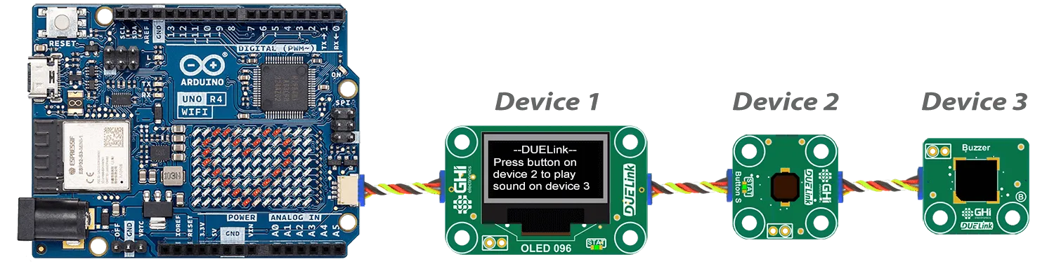
Here is another example that uses Arduino UNO 4 WIFI with an OLED 0.96 Display, a Button, and a Buzzer modules. Pressing the button generates sound on the buzzer, with the display showing some info.
#include "DUELink.h"

// This example runs on Arduino UNO 4 WIFI
// Device 1 is Display OLDE 0.96
// Device 2 is button
// device 3 is buzzer

TwoWireTransport transport(Wire1);
DUELink duelink(transport);

void setup() {
  Serial.begin(9600);
  Wire1.begin();
  duelink.Connect();
  duelink.Engine.Select(1);
  duelink.Graphics.Clear(1);
  duelink.Graphics.Text("--DUELink--", 0, 10, 1);
  duelink.Graphics.Text("Press button on", 0, 1, 21);
  duelink.Graphics.Text("device 2 to play", 0, 1, 31);
  duelink.Graphics.Text("sound on device 3", 0, 1, 41);
  duelink.Graphics.Show();
  duelink.Engine.Select(2);
  duelink.Button.Enable(1, 1, 1);
}

void loop() {
  delay(100);
  duelink.Engine.Select(2);
  if (duelink.Button.Up(1) == 1) {
    duelink.Engine.Select(3);
    duelink.Frequency.Write(7, 1000, 50, 0.5);
  }
}
Standalone
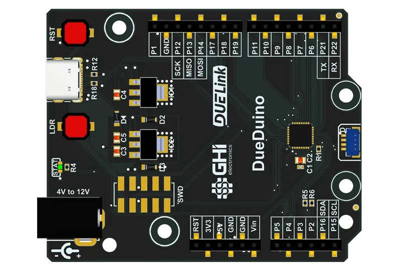
Any DUELink module can be run Standalone using the Arduino software, replacing the default DUELink firmware. An example will be DueDuino.
The chip used on al DUELink modules is STM32C071, which is fully supported by the Arduino IDE through the ST extension. But wait, we did not just leave it at that! We have a board support package for you.
Arduino standalone samples for DUELink modules are provided in their individual product pages. Those make for a great starting point.
Start the Arduino IDE. Under File, navigate to Preferences then click Additional boards manager URLs: icon. In the new window, copy and add both URLs below then click Ok.
https://github.com/ghi-electronics/duelink-libraries/raw/main/arduino/BoardManager/package_duelink_index.json
https://github.com/stm32duino/BoardManagerFiles/raw/main/package_stmicroelectronics_index.json

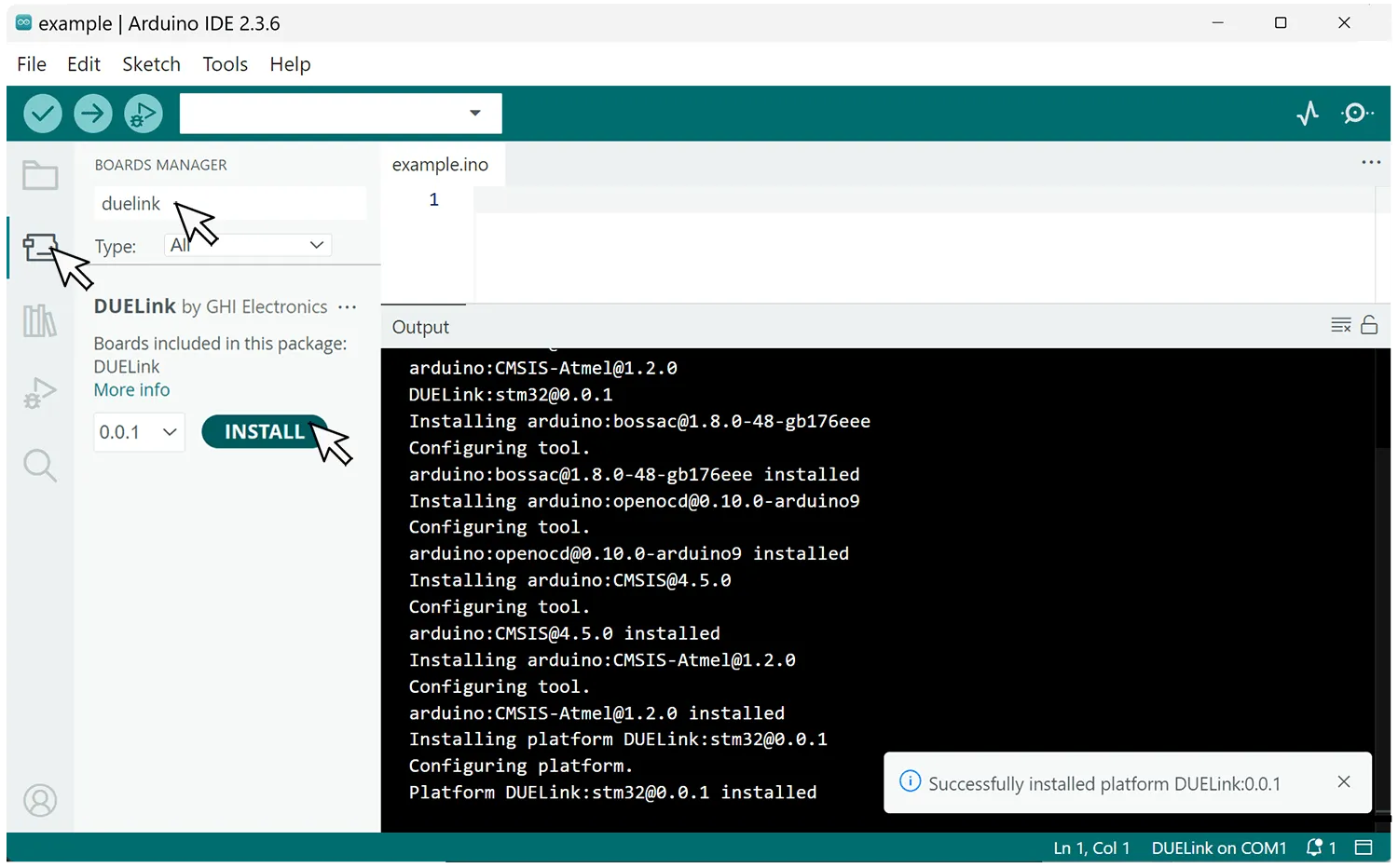
After the URLs have been added we can now add the "board". Select the Board Manager Icon from the side menu and search for duelink then click Install.
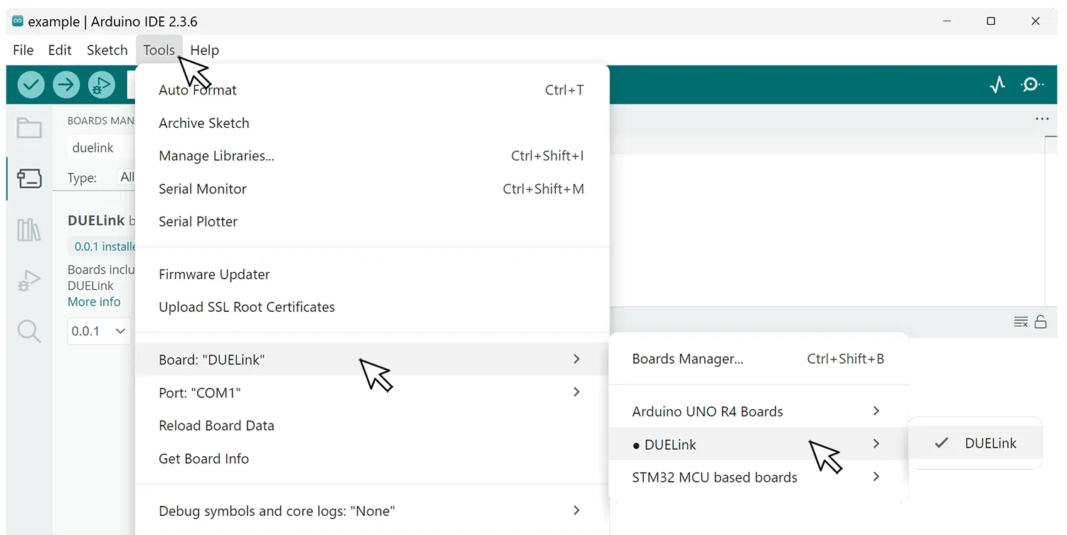
Finally we need to select the newly install board. Under Tools select Board:, then select DUELink.
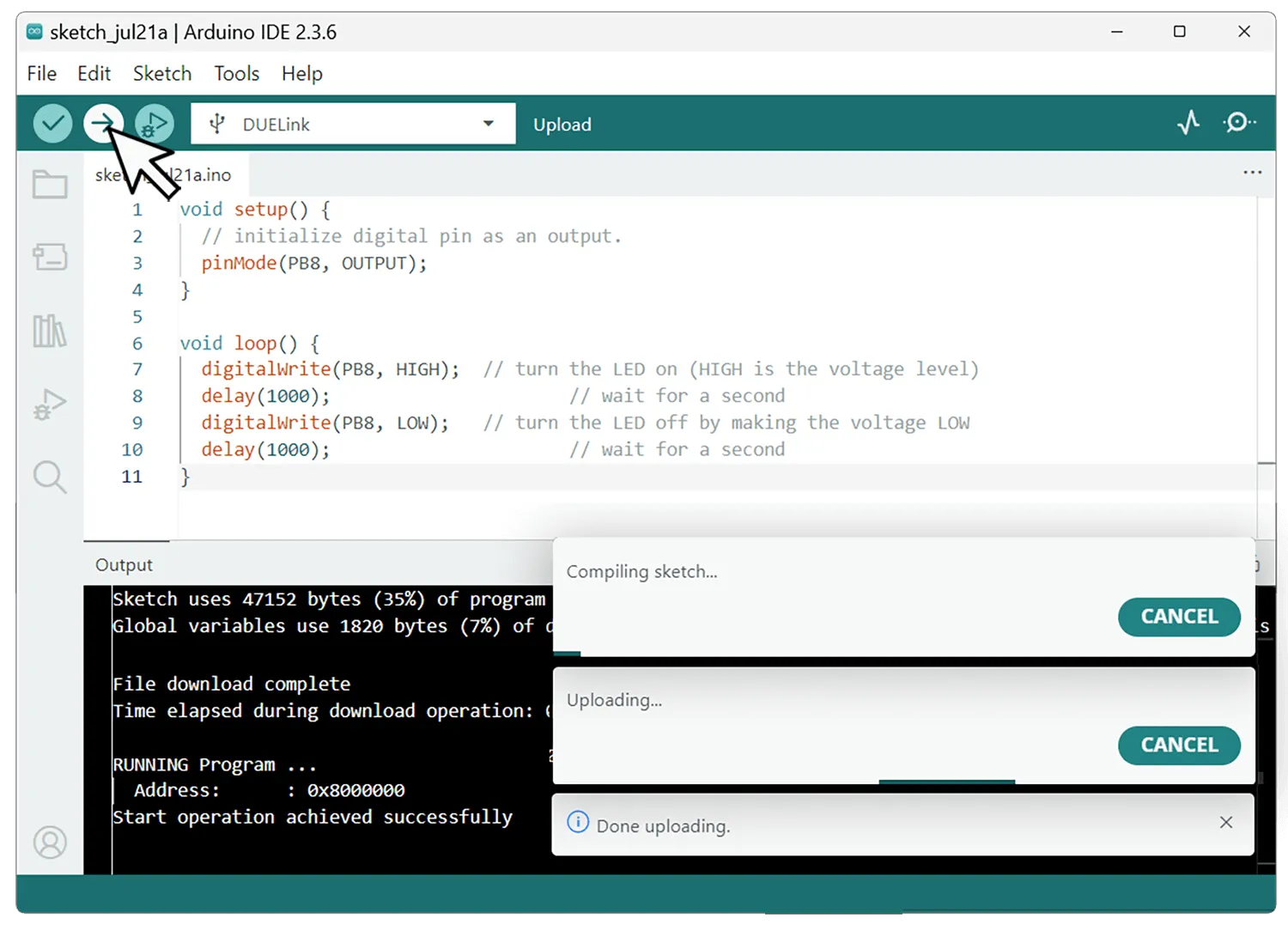
Add this code to blink the status LED, which is connected to pin PB8.
void setup() {
  // initialize digital pin as an output.
  pinMode(PB8, OUTPUT);
}

void loop() {
  digitalWrite(PB8, HIGH);  // turn the LED on (HIGH is the voltage level)
  delay(1000);                      // wait for a second
  digitalWrite(PB8, LOW);   // turn the LED off by making the voltage LOW
  delay(1000);                      // wait for a second
}
To load the Arduino program, put the board in loader mode (DFU) by holding LDR or "A" button down while resetting the board.

If no button is found, there are special 2-hole-pads (BOOT0 - 3.3V) found on the module. Use a paper clip (or a wire) to short the two pads. Reset the board or cycle power then remove the paper clip.

Click on the Upload arrow, this will compile the sketch file and upload it to the device.
Theory of Operation
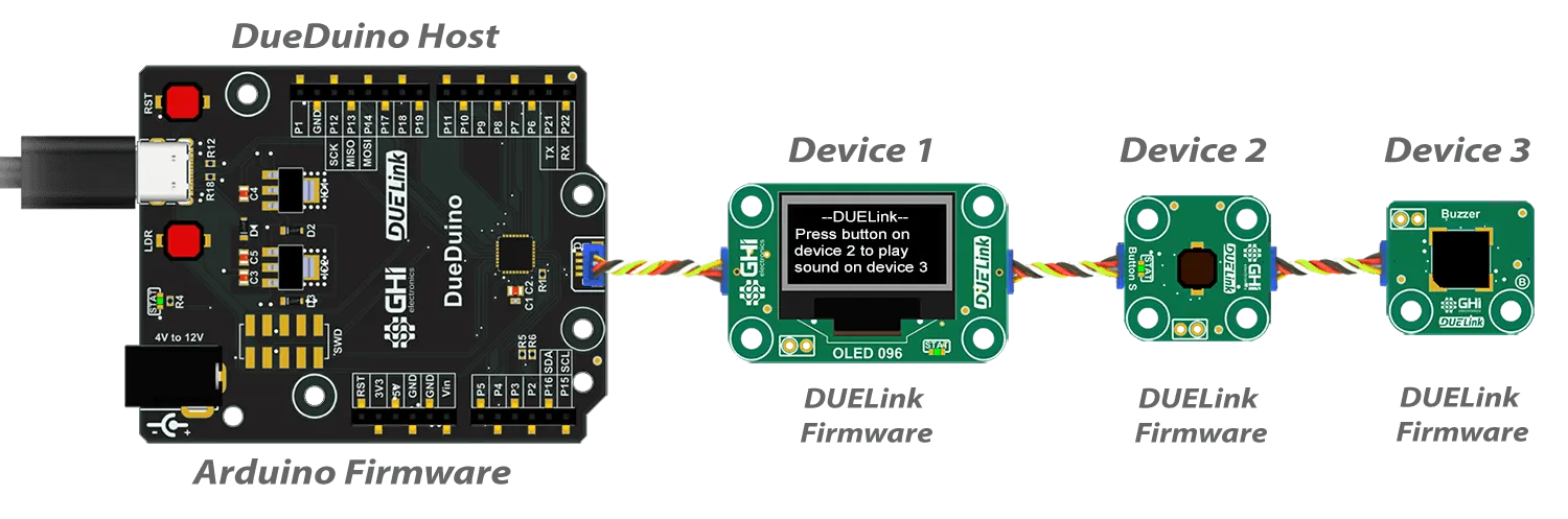
Loading Arduino software onto any DUELink module, turns it into an Arduino board. You will need to rely on the provided board schematics and the standard Arduino libraries for accessing the module. When a chain of Daisylinked modules are used, the first one will be running Arduino software. This first "module" is the Host. Just like you did with other non-DUELink boards, this host (a DUELink board in this case) can use the provided Arduino DUELink library to access the Daisylinked modules.
Note that the linked modules must continue to run the standard DUElink firmware. These modules have the usual DUELink addressing, but DueDuino does not have an address as it is the host.
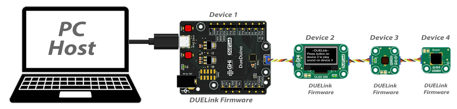
In comparison, when Arduino is not used, and the host is the PC for example, DueDuino has an address like any other module, because it is not the host. You can now use a coding language, like Python, on the PC to control IOs on DueDuino and the other modules.
Any module can run Arduino and can be a host, like a CinoBit. We are using DueDuino here for demonstration purposes.