Specifications
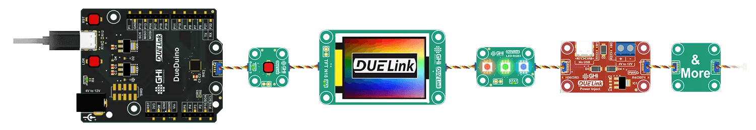
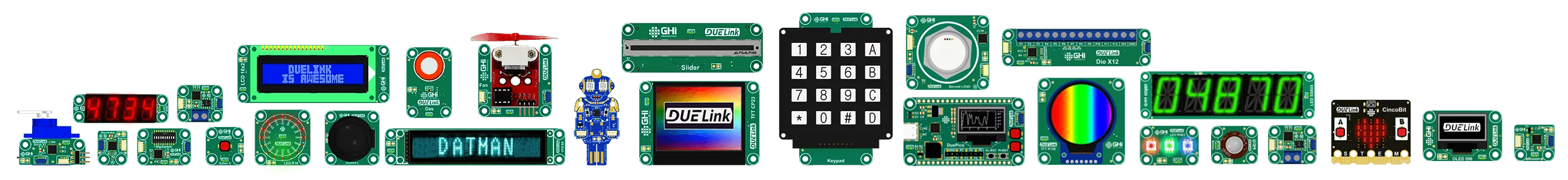
DUELink unifies many aspects allowing modules to come in any shape and form and still conform to a unified user experience.
Connections
Connections between modules is accomplished using standard 4pin 1mm pitch JST connectors.
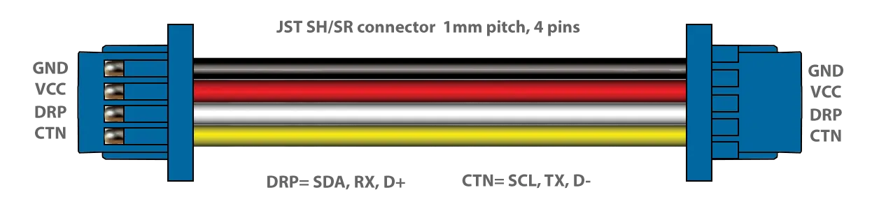
The pinout consists of:
- Common Ground
- Regulated 3.3V
- DRP
- CTN
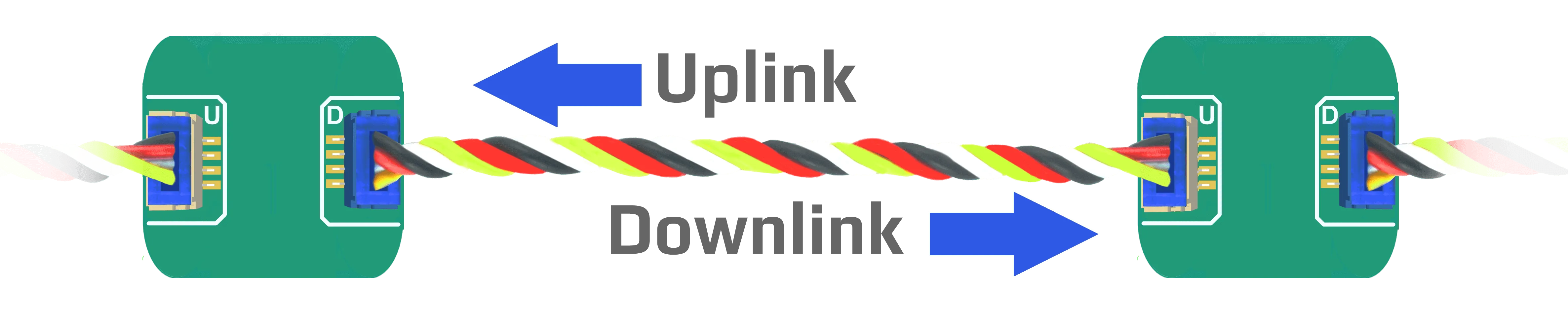
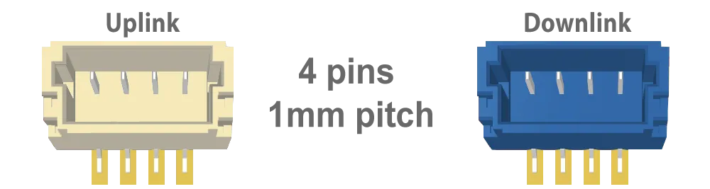
Each module includes both Uplink (white) and Downlink (blue) connectors.
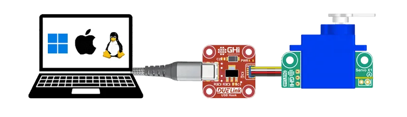
The Uplink connector is used to connect the module to a supported hardware, such as Raspberry PI or Arduino, or a PC. It automatically works with I2C, UART, and USB.
On UART, the pins are named from the module's perspective. The RX signal (pin 3) connects to TX on your board, and TX signal (pin 4) connects to RX on your board.
When USB is mostly desired on specific boards, a USB C connector is used instead of the JST Uplink connector. This is the case with DueDuino for example.
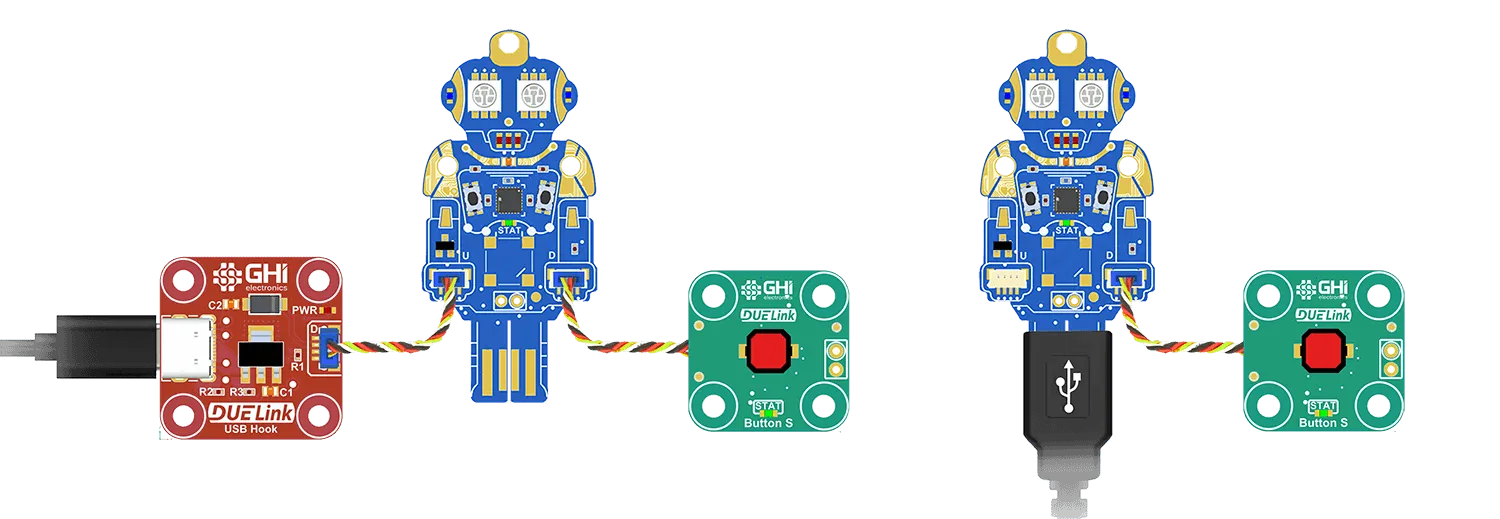
Every single module can still access USB by wiring a USB connector to the Uplink connector. We also offer USB Hook for convenience.
In some rare case, a module might have both Uplink and USB connector, like we have on Ghizzy. In this case, the user can use either USB or Uplink as they are both wired together internally.
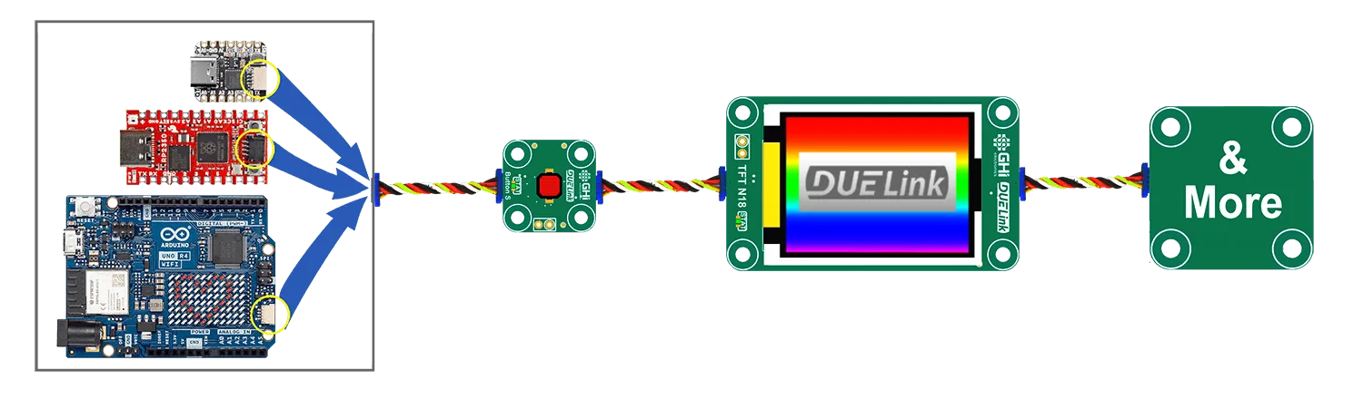
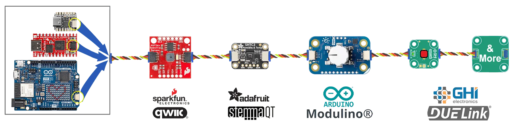
DUELink Uplink connection is compatible with Sparkfun Qwiic, Adafruit STEMMA QT, and Arduino Modulino. All use I2C, which is one of options available on any DUELink Uplink connection.

Always connect the non-DUELink modules first in line with the microcomputer and then add as many DUELink modules as the wires can handle!!
The second connector is Downlink. It connects to the next modules' Uplink connector.

Each module has intelligence to know what to transfer and return throughout the entire stream. Only connect DUELink modules on the Downlink connection. More details are on the Downlink page.
Uplink JST connectors must be white, while Downlink JST connectors are blue. The Uplink and Downlink connectors must also be clearly marked with U and D respectively.
Tip: When looking at the front of the module, we recommend placing the U connector on the left side, with D connector on the right.
Voltage Levels
All DUELink modules run using 3.3V. This section is only when mixing DUELink with non-DUELink circuits, when building your own custom electronics.
All Interfaces on DUELink modules are 5V tolerant. This allows all modules to work with 5V system, like the classic Arduino UNO for example.
While DUELink modules are okay with 5V, some non-DUELink circuits may not work with 3.3V levels. The reason is that some of those 5V circuits expect a high-level of 3.5V (5V x 0.7) which is higher than 3.3V. Other circuits, like some Arduino boards need a high level of 3V (5V x 0.6) and this will work fine with 3.3V levels.
An example of circuits that may not work are smart LEDs, which expect 3.5V (VDD x 0.7). The solution in this case is to use 5V buffers, or to power the LEDs using 3.3V to 4V. The LED datasheet does not list a minimum voltage source, but we have tested the ones we have with a 3.3V power source and they worked fine!
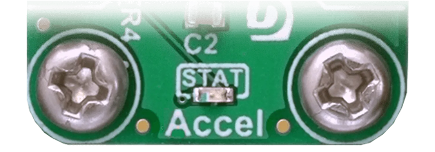
Status LED
Each DUELink module must include a STAT (Status) LED. This is used by the system automatically and also accessible using the StatLed() command. On boards that have parts on both sides, STAT LED must be on the front face of the module.
On power up, the STAT LED turns on automatically. It stays on until the device is ready. A ready device means it has selected an Interface and it has an address. At this point, the STAT LED becomes an activity-LED.
The status LED is also available to the user through the StatLed() API. It is up to the user to control the LED manually or leave it as an activity-LED.
Dimensions
DUELink modules can be of any size and form; however, they must include mounting holes that are placed on a 5mm grid. On boards with right angle corners, holes must be placed 3.5mm from the edges of the circuit. Holes are 3mm diameter with 6.6mm circle around it with copper keep out.
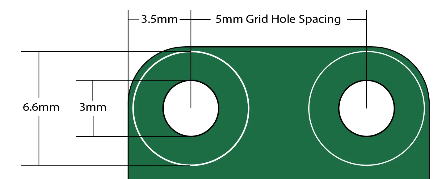
This allows for the use of M3 screws and hardware without worrying about creating circuit shorts.
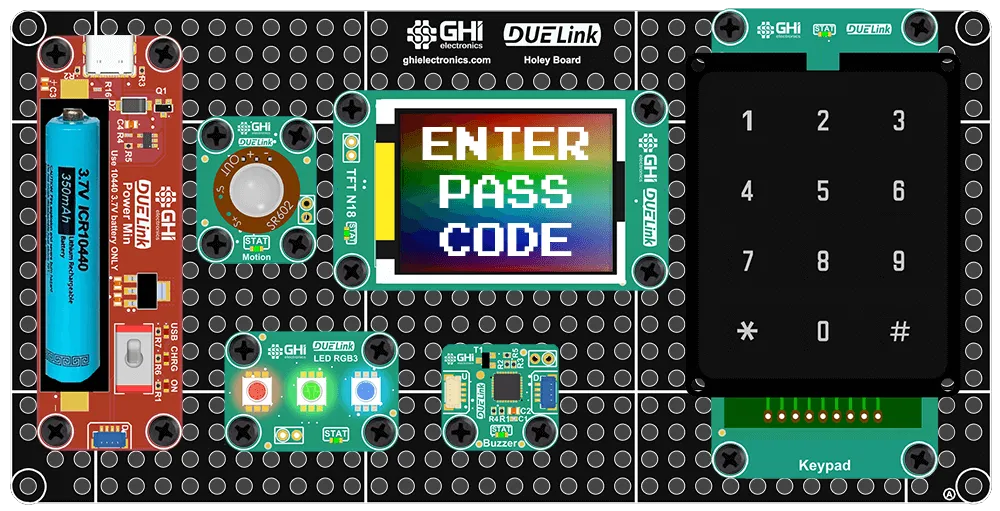
The 5mm grid placement of holes aids in 3D-print and laser-cut enclosure designs. It also allowed us to make Holey Boards!
DUELink Accessories include Mounting Hardware options.
Processor
Currently, only STM32C071 is supported with DUELink. We use QFN32 package but, fear not, we have made Stick to help you make your own modules!
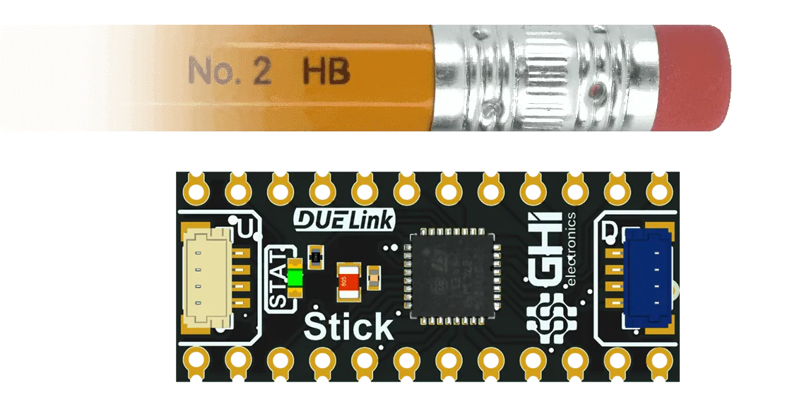
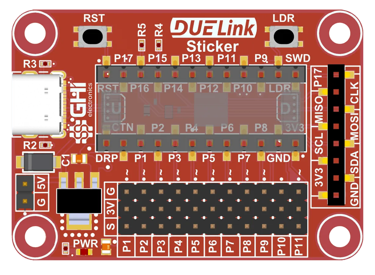
The DUELink Sticker is a mini development board that uses the Stick to help you get started.
Internal Temperature
The microcontroller used on DUELink modules has a built in core temperature sensor. This serves two purposes. On modules that might warm up due to driving loads, like on MotoTwin and Load, the temperature reading can indicate a system over load. On modules that do not warm up, like on Accel and LED R16, the temperature reading provide an estimate on the ambient temperature.
Color
We recommend to always use green PCB for all standard modules. Use Red PCB for modules that do not have an address. These Red modules can be something that bridges connections, like USB Hook, or a power module like Power Inject. Microcomputer category of modules are recommended to be Black.
Specialty boards are "special"! They can be of any shape and any color. The Holiday Tree is Green for example.
Custom Modules
We encourage everyone to help in growing the ecosystem by making modules to be sold commercially or for fun! Visit the Third Party Module page to see how we can help you.