Graphics
The graphics support is versatile and supports drawing on displays and LEDs of many types.
The graphics libraries do not include any device initialization. An application must initialize the device as necessary with GfxCfg() before using any drawing functions, like in the examples below.
Configuration
Before any drawing operations, the system needs to know what device it will access and what pixel mapping it needs to process internally.
GfxCfg (type, {cfg}, width, height, mode) is needed to set the device type with width and height. The {cfg} depends on the device type.
When mode is 0 then graphics is sent directly to display. No need for internal buffering and no need for Show(). This uses a lot less memory.
When mode is more than 0 then the engine uses buffering for graphics, where the value is the pixel multiplier. For example, setting mode to 3 will cause the graphics engine to multiply each pixel 3 times horizontally and vertically, 9 pixels in total. A 320x240 display runs at 106x80 pixels.
When selecting to use graphics with mode set to more than 0 (use graphics buffering), make sure the overall memory need is under 10KBytes. 320x240 with 3x multiplier is 106x80, needing 8,480 bytes.
Supported device types:
| Type | Description | Configuration {cfg} |
|---|---|---|
| 0 | None (default) | Graphics is not being used! |
| 1 | I2C Display | The I2C display's {address}. |
| 2 | SPI Display | The SPI display's {chipselect, control} pins. |
| 3 | NeoPixel WS2812 | {pin, pwidth, pheight, scan}. Configure for LED matrix connected to pin, with individual panel width pwidth and height pheight, with scan horizontal (0) or vertical (1), mirrored horizontal (2). |
| 4 | LED Matrix Scanner | {cfg} the first element sets for common-cathode (1) or common-anode (0). Then followed by data pin then scan pins. The width and height are used to determine how many pins are used for data and scan, respectively. |
| 5 | LED Matrix List | {cfg} contains a 2D list of LEDs pins, with width and height layout. |
| 6 | ePaper (eInk) Display | Uses {pixeldir, chipselect, control, busy} where pixeldir is 0 for horizontal and 1 for vertical pixels. Then pins used with SPI bus. |
Not all types support both direct and buffered modes. See individual modes for supported types.
Drawing
Depending on the graphics configuration, these drawing functions can either draw directly to the display, or draw to an internal buffer than can then be shown using the Show() method.
| Function | Description |
|---|---|
Clear(color) | Clear the buffer to color. |
Pixel(color, x, y) | Sets a color pixel at x,y. |
Circle(color, x, y, radius) | Draw a color circle at x,y with radius. |
Line(color, x1, y1, x2, y2) | Draw a color line starting at x1,y1 and ending at x2,y2. |
Rect(color, x, y, width, height) | Draw a color rectangle at x,y with width and height. |
Fill(color, x, y, width, height) | Fill an area with color, starting at x,y with width and height. |
Text("text", color, x, y) | Draw 7x5px text with color at x,y. |
TextS("text", color, x, y, scaleWidth, scaleHeight) | Same as Text() but adds scaleWidth and scaleHeight. |
TextT("text", color, x, y) | Draw a tiny 5x5px text with color at x,y. |
Img({image}, x, y, w, h, transform) | Draw an image at x,y with transform: 0 = none, 1 = 90 deg, 2 = 180 deg, 3 = 270 deg, 4 = Flip horz, 5 = Flip vert. |
ImgS({image}, x, y, w, h, transform, scaleWidth, scaleHeight) | Same as Img() but adds scaleWidth and scaleHeight. |
ImgB([image], color, x, y, w, h) | Send binary array imagedata, with color, starting at x,y with width and height. |
Show565([image], x, y, w, h, hscale, vscale) | Shows a 5:6:5 color image that has a w width and h height at x and y, with scaling. This function only works on SPI displays in direct mode. |
Show() | Transfer and show the graphics buffer onto the configured device. |
Scripts running on a module itself can access these functions directly, using Text("DUELink",1,5,5). Supported coding languages libraries include wrappers for accessing the graphics functions, like duelink.Graphics.Text("DUELink",1,5,5). The module itself can also run in host mode and send the commands to other daisylinked modules Cmd("Text(\"DUELink\",1,5,5)")
In direct mode, drawing goes directly on the display, where Show() doesn't do anything.
These are a few samples showing how to use graphics in multiple languages. The samples assume the module was loaded with the Driver Script which has the graphics configuration.
Samples
- Script
- Python
- MicroPython
- JavaScript
- .NET
- Arduino
# Clear screen with black color
Clear(0)

# draw text white color, at x = 5, y = 5
Text("DUELink",1,5,5)

# flush to screen
Show()
# Clear screen with black color
duelink.Graphics.Clear(0)

# draw text white color, at x = 5, y = 5
duelink.Graphics.Text("DUELink",1,5,5,1,1)

# flush to screen
duelink.Graphics.Show()
// Clear screen with black color
await duelink.Graphics.Clear(0)

// draw text white color, at x = 5, y = 5
await duelink.Graphics.Text("DUELink",1,5,5)

//flush to screen
await duelink.Graphics.Show()
// Clear screen with black color
duelink.Graphics.Clear(0);

// draw text white color, at x = 5, y = 5
duelink.Graphics.Text("DUELink",1,5,5,1,1);

// flush to screen
duelink.Graphics.Show();
# Clear screen with black color
duelink.Graphics.Clear(0)

# draw text white color, at x = 5, y = 5
duelink.Graphics.Text("DUELink",1,5,5,1,1)

# flush to screen
duelink.Graphics.Show()
// Clear screen with black color
duelink.Graphics.Clear(0);

// draw text white color, at x = 5, y = 5
duelink.Graphics.Text("DUELink",1,5,5,1,1);

// flush to screen
duelink.Graphics.Show();
Smart Displays!
Some applications require several graphics updates every second. In this case, it is best to load a display with a script that updates the graphics internally, to build the user interface. For example, a thermostat smart display demo can use the screen get the user's desired temperature. The desired temperature can then for example be stored in _t variable. You now can read the _t variable, from Python for example temperature = Engine.ExecuteCommand("_t").
This is also the case when needing to draw images, as sending buffers over the Daisylink connection may not be desired. In this case, the image data is stored and drawn within the display module itself.
Color
All color arguments take 24BPP format RRGGBB, similar to what is used on the web.
When using direct mode, the full color is used and drawn on the display directly. However, in buffered graphics mode, the system reduces the color depth from 24BPP to 8BPP 3R3G2B (256 colors). Those pixels are then stored (buffered) in memory. Calling Show() transfers the graphics memory to the display.
Neopixel graphics mode is an exception here as it always buffers/draws in full 24BPP color depth.
To simplify working with black and white displays, color 1 is a special color that results in white 0xFFFFFF. Clear(1) and Clear(0xFFFFFF) do the exact same thing, clearing the display to full white.
With 8BPP 3R3G2B, Red and Green are 3 bits, giving you 8 levels each (7 levels plus off). Blue is 2 bits, giving you 4 levels (3 levels plus off). 256/7= 36 => Red and Green change every 36 steps. 256/3=85 => Blue color changes every 85 steps.
While you can do 255 colors in 8BPP, here are 16 common color examples:
| Name | Value | Color |
|---|---|---|
| Black | 0x000000 | |
| White | 0xFFFFFF | |
| Full Red | 0xFF0000 | |
| Full Green | 0x00FF00 | |
| Full blue | 0x0000ff | |
| Yellow | 0xFFFF00 | |
| Cyan (Aqua) | 0x00FFFF | |
| Magenta (Fuchsia) | 0xFF00FF | |
| Gray | 0x808080 | |
| Silver | 0xC0C0C0 | |
| Maroon | 0x800000 | |
| Olive | 0x808000 | |
| Navy | 0x000080 | |
| Teal | 0x008080 | |
| Lime | 0x32CD32 |
Images
There are two ways to add images, with a "color" per pixel, or a single binary bit per pixel.
Color
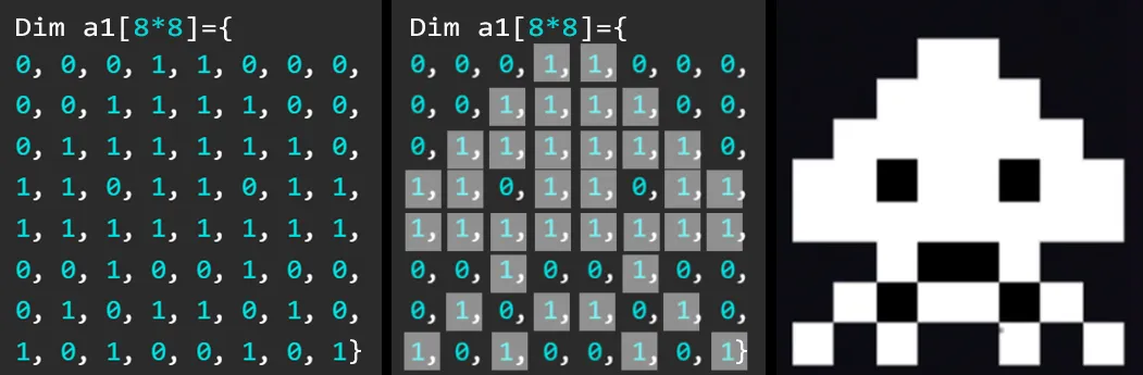
The Img() function uses a color array bitmap to create an image. These arrays can sometimes be visualized when looking at the array.
Dim a1[8*8] = {
0, 0, 0, 1, 1, 0, 0, 0,
0, 0, 1, 1, 1, 1, 0, 0,
0, 1, 1, 1, 1, 1, 1, 0,
1, 1, 0, 1, 1, 0, 1, 1,
1, 1, 1, 1, 1, 1, 1, 1,
0, 0, 1, 0, 0, 1, 0, 0,
0, 1, 0, 1, 1, 0, 1, 0,
1, 0, 1, 0, 0, 1, 0, 1}
Clear(0)
Img(a1,50,35,8,8,0)
Show()
This example below creates the same sprite using colors set to different elements of the sprite. Note the use of Alias() to make the code more readable.
Alias(body=0x00ff00,hat=0xff00ff,legs=0x0000FF,back=0xFFFFFF)

Dim a1[8*8] = {
back,back,back,hat,hat,back,back,back,
back,back,hat,hat,hat,hat,back,back,
back,body,body,body,body,body,body,back,
body,body,back,body,body,back,body,body,
body,body,body,body,body,body,body,body,
back,back,body,back,back,body,back,back,
back,legs,back,legs,legs,back,legs,back,
legs,back,legs,back,back,legs,back,legs}
Clear(1)
Img(a1,50,35,8,8,0)
Show()
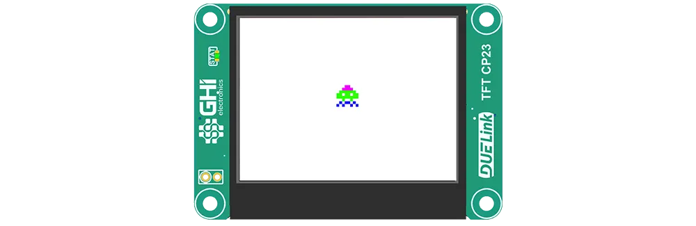
Binary
The ImgB() function uses a binary array in direct mode. This allows for larger images with very little memory, 8 pixels per byte!
ImgB([data],color,x,y,w,h)
Users can take advantage of 0b0000000 to use binary numbers to create an image.
ImgB(b1,0x1377AB,20,30,24,8)
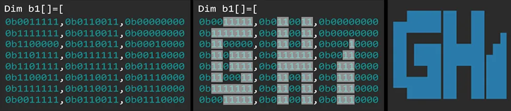
Additional binary arrays can be added to create multi-color images.
ImgB(b1,0xFAA957,20,30,24,8)
Finally the Show() function is called to display the overlapping image arrays together.

Dim b1[] = [
 0b00111111,0b01100011,0b00000000,
 0b01111111,0b01100011,0b00000000,
 0b11000000,0b01100011,0b00010000,
 0b11001111,0b01111111,0b00110000,
 0b11001111,0b01111111,0b01110000,
 0b11000011,0b01100011,0b01110000,
 0b01111111,0b01100011,0b01110000,
 0b00111111,0b01100011,0b01110000,
]
ImgB(b1,0x1377AB,41,32,24,8)

Dim b1[] = [
 0b00000000,0b00000000,0b01110000,
 0b00000000,0b00000000,0b01100000,
 0b00000000,0b00000000,0b01000000,
 0b00000000,0b00000000,0b00000000,
 0b00000000,0b00000000,0b00000000,
 0b00000000,0b00000000,0b00000000,
 0b00000000,0b00000000,0b00000000,
 0b00000000,0b00000000,0b00000000,
]
ImgB(b1,0xFAA957,41,32,24,8)

Show()
Show565
There is a special function the "show" a 5:6:5 16BPP image on SPI displays when used in direct mode.
# Show a 64x54 cat image
# The display must be initialized and ready in direct mode
dim b1[] = base64("MSQxRDFkMWQ5hDmFQaVB5koHUkdiyXuMlE+k0a0StTO9lL21zdfN9832vXSbzKxuxTHNk820vXO9lLV0tVStM60SrRKs0aTQpLCkj5xunG6cTpxOnE6cTpROnE6ULpxOpE6sjqyPvTG9MZwNpG/WFdY21jbWFtYW1jbWNtY21hYxRDFEMWQxZDmEOYVBpUHmSgdSJ2Kpe2yUL6SxrPK1M7WUvbXN1s33zhe1M4uLm+ybzKxvvTLFlLVTvXO1U7UzrRKtEqzxrNGksKSwpI+cbpxunE6cTpQNnC6cTpQOnG6kTqRurK+sj5wNg2qUDdYV1jbWNtYW1hbWNtY21jbWNjFEMUQxZDFkOWQ5hUGlQcZKBlInWohzS5QOpLCs8rUztZS9tc32zfbOFqSQg0qb7KxOk6ycTsVzvXO9U71TtTO1Mq0SrPGs8aTRnI+cb5xvnG+cTpxvnE6UDZxOnE6cLqRupE6kbpwNi4tzCZwu3hbWFdYV1hbWFtYW1jbWNtY2MUQxZDFkOWU5ZDmFQaVBxknmUidaiHMrjA6kkKzytTO1lL21zfbOFs4Wi+17CaxOtLCsb4Nrk+y9Ur1SvVO1MrUyrRKs8azRrPGkkJyQnI+cb5xOlA2cTpxunC2cTqROpE6cDZPsnA2T7HLorLDWFdYV1hXWFtYW1hbWFtYW1hYxZDFkMWQ5ZTlkOYU5pUHGSeZSJ1qIcyuL7qSQrPK1M72UvbXF1s4WzjaMDYMqpC60sLzxrI97CZPMvVK9Mr0ytTK1Eq0SpNGk0aSwnJCcb5xPnE+cTpxOnC6cTqROnA2Tq5PMnA2kbpxOcum08dX11hbWFtYW1hbWFtYW1hbWFjFkMWQ5ZTllOWQ5hDmlQcZJ5lIHWmhrCovNnJCs8rUytXPFtc3WzfbONpxvk6ysb7zxvPG9EaROgymcDcVSvVK1Eq0SrPGk0aTRnJCccJxvnG+ULpxPnA2cTqROi6uDSpPMpC600LTQrG+Di71S1fXWFtYW1hbWFtYV1hXWFdYVOWU5ZTllOWU5ZDmEOaVBxknmSgdaaGrqg62ccKzxtRK1U8W1zdbN9s42rPGkLrzQvNC80LzQvPCb7ItqpC20sLUytTKtEq0SrPGk0ZyQnJCUT6SQnG+cTpwNewlqhouKpE60r7zxrLCkT5wuxZTV9dYV1hXWFdYV1hXWFdYV1hU5ZTllOYU5ZTlkOYQ5pUHFSeZKB1JHYsmDrJxvrNG1ErVTxbXFtc4Xzje1MqROvNC0j8TxxPG88KxNi2qLanrog4uL7YOscypiyWsKYqlKBmKpYohiiHMJaqdqhpOKk4usTrSwrG+kTpvtnC7FlM3V1hXWFdYV1hXWFdYV1hXWFTllOWU5ZTmFOWQ5ZDmFQcVJxkoHUkdiyXuMlE+k0bUStVO9lM3WzhfOF72UnC688c0yxRHNMrzQtI+TinKGcqdBQknlQYQowTEiKOIxIykCOYQowUmkUeRaJXsIcqeDSZvstK+sr6ywpE+ssM2UzdXV9dYV1hXWFdYV1hXWFdYVMWQxZDFkOWUxZDFkOYVBpUnmSgdSR2Kpe2yUL6TRtRK9c72UxbbN1843zfacDbSPvNC0bqxOvLDEsKPsiymDCHLIe0p7KlpnSeUxIzlDUidSBlpHeyp7KXLIamZyhpOqrI+sbqROpE6kTrTxzZTFlM311hXWFdYV1hXWFdX11hU5ZTFkOWU5ZTFkMWQ5hUGlSeZKB1InWoh7S5QOpLG1ErVTvZTN184YzhfF1YusrG680LyPxLDE0LyvvK60baPsi4uDSkmkYmdaJkGkQaVSJ1pnUgWLjJPMpE6cDJOKpAy88LzwrG+kLoNKtPHFc83UzfXWFdYVzhXWFdX1zfXV9TllOWU5ZTmFOWQ5ZDmFQaVJxkoGUidaiHMri+6ksK0StVO9dMW2zhjOF831k+ybzKwNtE68j7ROvK+8rpvLk2mTq4NrMMBiRmKoYqhqyXMqYog5Q3spg2uLi5OrrG6sjqxutK+sj5wti4u08b1SxbTN9dYV1hXOFdX1zfXN9c31OYU5ZTllOYU5ZDFkOYVBpUHGSeZSJ1qIcwqL7qSQrRK1U72UxbbN1s4W1ja0sIspguiLCbxuxK+8r7Rto+uTqpOKi4pJg2qHnA1yyVIGg2t7SzkCeyqLi4NKg0mby6xNrE6b7INKg0qcDb0yxVPFk83V1fXWFc4VzhXN9c31zfU5ZTFkOWU5ZTlkOWQ5hTmlQcZJ5lInWmhrCovNnJCtErUzvZXF1s32xhbOFsVSk2qC6KvszPDEz7xtrCyj65Oqi2mTq2pmSaOsj2rIWiaT7WqoScSDSnsJi4ucDYtqk4q0j6RNewlqp5PMvTG9UsW0zdXN9c4VzfXOFc31zfXN9TFkMWQxZDFkMWQxZDmEOaVBxUnmSgZSR2rqg62ccKzytVO9dL2VxfbONs4VxVKTi5uLvI7Er7xttEy0bZvLi0lyx5OKrG5RxINqaqhqqINrSYOcDYMqYkZ7CYNJk+yTq6QMrI6kLXronC208L1SvXPN1M31zfXN9c31zfXN9c31MUQxRDFEMUQxRDFEMWQ5hUGlSeZKBlJHYsmDjJxPrPG1M72UxbXF1cYVzfTFMZNqm6vEz7yurCysLKPrguekLGpmWeS88HLHaod7CWqneulSBbTwWeViRpPMYmaDSZOrk4qkLZwMewmcDbURvVLFc820zfXN9c31zfXN9c31zfUpJCkkKSQxJDFEMUQxRDmEOaVB5koGUkdiqXtslC+k0bUztVPFtMXVxdXN9bTQk4q8rrSNrCysLLRtm4pqJKwsewk5AbzwnAxiRouLk8x7CYuLrK8w4Hrpm+1aJXrHk4qLSYtJm+x7KZPMtRG9MsVzxbTN1M31zfXN9c31zdXN9SkDKQMpAykDKSMpIzEjMWQ5hUHFSeZSJ2KJe0uUDqSxtRK1U72UxbTN1cW0k+2Tq7yurEyj67yuvK+sLZurrE288FoEtK60rqRNnA2kLaxvpG6kLUmDpE6kTouLk6uby5OKiymTq3sIg0q00L1SvVLFtM3UzfXN9c31zfXN1c31IOMg4yDjIOMpAykDKQMxRDlkQaVJxkoGWohzK4vunJCs8rVUtXS9dM3VxXSb7aQttG20K7RMzQ/FD4tpcuhqp6QtzVHEzpOJpCysbrzQpC2LSaRNtK+cLWJnYod7KaxunAyDKYNJeymDSqzQtRG9c8WTzdTN1M3UzdXN1c3VzdUgwiDCIMIgwiDiIOIo4ykjMWQ5pUHGSgZaaHMKi82ccKTStTO1VL10xbW1MqyPrE20TMSNxM68bGplYkVaZzmDWiSsje4ztCyTiqxNtI+DKYtpxXGLqkGjKQI5hFHEUcRyp4NKi4ty6INrpG+1Eb0yxXPNtM3UzdTN1M3UzdXN1RiBGKEYoRiiIMIgwiDCKQMxIzmEQaVJ5lpHauqDrZRPnNGtErVTvXO9c6zQpE2by7yutG16ZZMoakWkj4OtUmh7aouqvO/dsryOrC2bzJOrtM+cLVIEg8wxY0pGg2xyqHKoOQFqh2JGaoeT7bTxvTK9c8W0zdTN1M3UzdTFtM3VGGEYgRiBGIEYoRiiIKIg4ikDMWRBpUnmUkdqyXtsjA6csKTxtRK9U71SrK+Ty5vLm6tZgmHDxO+DSaSPSgYYoZRNg6p6x+XzxM+sLKPLm+y08EnDWmaMDSkhYul7KouMnA0w4SBgUgVaRoOLtTK1Eb1SxZPNtM20zbTNtMW0zdUQQBBBEEEQYRiBGIEYgSDCKQMxRDmFQcZSJ2Kpe0uL7ZxwpNGs8bUSvRKkTouLi6tZxEEBgwi876QsaqeLzIOLpI5BYVGi1XHND7xstCu0TKRNMSEowHMIg6tzCIMJrI9qqEmkIIAw4UnFi82s8bURvVLFk8W0xbTFtMW0xbTFtBAgECAQIBBBEGEQYRhhGKEg4ykjOYRBxUoGWohzK4OtlE+kkKzRtPK08Yusg0pyqFHEeuh66IMoxTCcDHsog2lyxmJEUWGbisStvGy0K6vqaoY5AVolg0mLiqQMtG6DCVHlOWNJxTECQYRzKqywtPG9MsVzxZPFk8W0xbTFlMW0ECAQIBAgECAQQRBBEGEYgSDCKQM5ZEGlSgZaaGsKg4yUDqRvpLC08ayxk+57CnLpaoeLamJFgwiTirzvzVDVcOYTrCxRQXJlo8q0K6OIiuZyRUlCi0rd09WyvM6LSWIlQUMxIknFOWMo4UGli82s0bUSvXPFlMVzxZTFlMWUxZQQIAggECAQIBAgEEEQQRhhIKIpAzFEOaVJ5lpoaup7bIvNnE6kkKzQrLGDjGqISWNyp4tqcsdyp4MIk4qjyryN1VCjyoLHeoZyZYsnkydqA1mCYeSLKaPsi0h6x1oEOQFBg2rpYohJ5TljOUNKBpQutRK1MsVzxXO9c8WTxZTFlBAAEAAIABAgECAQIBBBEGEYoiDiMUQ5hUnmUkdqyXtLi8yULaSPpLCksIvNaqhyyJOKm8uTimpFWcN6x5uKtCzErcSNo6pyJFmieqaCpmGjSSFqRaPMm6uLamqGUcRBg0FjQWNSJmKoQaUxIykCWoicT6zRvVPFc71zxXPFlMVzEAAQAAgAECAQIBAgEEAQQRiCIOMxJDmFSeZSR2LJcyuLzJQNnG+ksKSQi62DKpvMxRByZVFhgueC6HrHtG3E77RL5XDEjWGiaiWLKYsJeodAwHqGvK6by3rIk8xqiGqocslR5TkjOSNJxSkCIMExQ2KpnE+1Er1TvXO9c8WTvXMQIBAACAAQIBAgECAQQBBBGIEg4ikjOYVJxlInYqlzKoOMlA6cb6SQlA5qiHsqcqd6x2okiyjEz81RzVHNUaQLm4jVDt1wq+thpILJq+1ZY3qnxRC0jYtpgwiTzHsKcsliR1HlUiZBZEHFKQMYYCChMURzK6SQtRK9Ur1TvVK9cxAAEAAIABAgECAQIBBAEEEYgSDCKSQ5hEHGUidiiHMKg4yUD5xPnC57S2JGeul66HKGm6qbqpuJxQ/VcdWSzTC8jc0O7jT+17zRaidqJoLJ3fTV07yum8uby5Org0tyyWqIaqhiZ1HmOWQpAykjIMIgoUGlg62s0bUSvVO9Mr1zEAAQAAgAECAQIBAgECEQQRBhIMIpAzFkQaVKBmKIcyqDzYwOlA6LrHrpg0p66JOrk6ubzKxNrC28rtVRzVG8r8Tv1VHeFPb57rmLjElk3dXmVtXUtM+sTZuri4uDa3sqg0qLrIuMYog5hDlkOWQg4iChIMJaaJQOrPG9Mr0yvTIQAAgACAAIIBAgCCAQQBBBEGEgoikDMWRBpUoHYqlzK4PNg62LjIMqg0qkLXLIYiWLaoMqesiTirSO1VHNMsURzTHVs94V1ha9dINsYkissb1TvTK00Jvsgyl7CXMJWmdaJnLIaslaaGKpQcZBxUHGKOIgwTEjcyuksKzxvVK9MggACCAIIAggCCAQQBBAEEEYYSDCKQMxREGmUgdiqntsg417S4uMgypiJZOLewliJmJGm+2sLZuro+y8js0x1ZPFUr0RvRKs0aRQewtiiZPuk+6ULpxPk82Lq2qnYmZqyHLpculJ5UnmScZKB1InQeY5hSkjKQNKB5QPrPG1Eb1SCAAIAAggCCAQQBBAEGAQYBBhIMIpAzFEQcZaaWrre0x7K2rJk82DCVnki2pyyGImamd66IMJgwmC55NJk2qsbrzxxTLFMrTRxTPFdMV0xVSssZwvlA5zCVpGWiZJpHMJg2tih2KIWkhBpjmFQcZaiTmlKQMpAzlkc0yksbUytREIAQghECAQQBBAEEAQYRBgGKEgwikjOWVKB2LJcytzKnMKaqecDZvLWeSDCJvsaqdqZnrIk4p6x4tJk2qjzJOKiyqb7MUR1ZPV1M2UzZS88qRvg2taJlIGScVaJlIGQYRaRnMJeytiqUGFOWQxZEHmSicg4iDiMUNiypxPrRG1UgghECEQIRBBEEAQYRhhGIEYwiDCKQNBpVJoawpzKnLpYodqp5wNk6pRo4NJtK97CHKneuhyppOKk4qby7RtpAyTaoLok2qTapOsk4uLanLpaodiZ1omYmdaJkGEQYRaJ2KHcwlq6UnmUidBxikDOYRKBikjIMIpAlInlA6s0bURECEQQRBBEEEYYRhhGIEYgRiiGMIxREonYupzS3NKauliZ3KonA20roMpcseb66QsamZiBXsIk6qkDLRtpAyj66Prk0mTaoLoguh6yHrpcodqZmJmYkZJxEmkSYRJpFomculaRkGEUeZJ5jmlMSMpA0HFMYQgwiDiQcWDraSwrREQQBBBEEEQYRhhGIEYgRihGIIpAznGWolzK3tscypiiGJnYkab7MUQeuhiBINJgyl66GpmcqaTiqxNtI6sTbSNvI20TKxMrC20bqwtrE6b7YtqamZJg2JGWeVRxGqnaqhaZmKoOWNBhVpoMWQpAykDOaVBxiDiIOI5ZGsKnG+1ERBAEGAQYRCBGIEYgRihGKIYojFESihq6ntse2xiqUnlWiZiRotqrE6bzHrHYgVqZotqgwhqRYLoo+u0TbSOvM7E78UPxO+8z7zPvNC80KQNgwlqZ0lCWgRaBWIlewiT7GqoWiZBhEGEOYU5ZSDiMUQxQ0HGMUQg4ikDWmiULqSwEEAQYBBhEIEQgRChGKIYoiDjQaZiqXtsi857bFqIScVqyXLIamecDaxucqdqZpOLpAyTqmolcmabqqPLvG28jsTvvM7FEMTwxPDE8KxNk2pyhoMIYiViJWJFeuiLansJashBpFImWmgxIzFEOYUpIzFEOYUxZSkjKQNBxYOspLAQYRBhEIEQohCiEIIYohiiMWVSKGrqi+6T7ntsUidSJ3sqi4tRxXsJpA2DKXrHm6usbZurcmZiBHqmiyisDKwstI68rsTwxRC8rqxNm6pyhnqmeudqRYMIgylyp4NKWgVJxUnmWmhSJyDCGIExRCEDMWQxhSkkKSMpAzFkawqcbwhBEIEQghCCEKIQohiiKSRJ5mKJeyty6ntLcwpSBlHmi4ykTloFYkaTq6RNeuiLSbSum8t66HJlcmV6posIiyisLLyutI60baPrk2mLSILni0hyhnKGi2qTzFnlculaBjlDWmdaiSDiIMIYohihIQMhAzFkKSMpAyjjMSNaiJQuEGIQYhCCEGIQghiBIMJBpWKIe0t7S1omQWNSJlpHWkeT7KxvaodBQnrorE2TimpFo+ysTZOKi2mLSYMHiweLKJuqrAybqqPLi0ibipuqk4p6x3Kmgyl7CYNrUeUxIkGlSeZaaEGlIMIpAxjCEGEg4iDjKSMg4yDiKQMxRFJHjA4QYhBiEIIYghiBKQNBhEnFcumcLqRve0pJxVHlWkZqqJPMrK+DalHDSWKLaqxtcsZiJZOrnAykTZwMm8ubyqPrrCykC6QLpAusLKxNm8uC6GIlaoaLi1pGUeVJxUGlSeZiqUGlIKIg4xiiEGEQYRihIOIhAyDjIMMg4ykDSgaDzRBiEGIQYSChOSNiR4Nri4tR5GJmnA6UDmKHUgVih2qogymTzIurcsdBYlGjm8ukLHKGYiVy6IvLk8ycLZPLpCy0bbzOtG2kDJvLm8uC6GpmakZJg1oFSeVBpEoGSidB5koGKQIg4xiBEEEQYRCBEIEYgRiiKQMpAyDCKOJSJ4wOEGIYoikDUgaDKpvstG688INJMMBR5XMqScViZ3LpYkZiZoNKewly6GqnWgViRZwMtM9y6EGDQWNJpGKHcsiDaqyOpAyLaoMIesdqRXKHakZRxEFCQWNSBVImSgYpIxihIOIgwhBAAAAIIBBhEGEQgRBhEGEg4zFEKQMxZFqIg80IYSkDYqicDbSOtEyj6qwsnAxBYjDhUgYo4VIGculyyHLHYiVaJVoFi6ukTouLaoeLq4NrWidaaHtslA6LrXLpYmdqp3LIcqdiJXrogwly6HLHaqcxASjAUgYxQxBAGIExRDmFOaZaqkHnQedCBykkGMIYoikkQedSSGKqe2yMDhiiOYSDi5wLm4mjqZtoo6qby0mjIIAxQyCBScWDS3Kng0qDKWqHWkZy6YNraohyyZPtlA6UL6zztVStEpxPi81qqFGkYkZ66Itqk8xqhmJmk+ykTXspOWI5Y2LJKOIQIGLqnJGc0pSRnLKMUIPvhA9aqlJpYsp7jovvi++MD5RPKMJiiItpo8qryauomyd6ZYtJUeUQICjiKQI5Q4NLi2tqZmqHauhih2JnScWDjbUzvXS1U711vVTFlbTynE+UDpOrm+uTipvsi2pyx2JGQaNaRntKi8xzCTlkYqlBxjmFnJGUcKTSnJGUUZSRjC+ML4wvjC+csZSRlFCUUJRwlC8w4mJGpCy0S7QKq4iS5mGiWeRiRhiAGIEpAyCBasiT7YuLYmdSBWKoe2ukcLU0tRS1M7VTtTTFlcV0rNGksKSPpC2b65vLgud6x3sIasg5Y2rIYoeLi3MJYqhaiUnmjA+k0pyxpNKc0pyRlHGUcJRQjC+UcJyRlHCDzoPvlFCUcEEji2u0jaPJq8mbJoKFagM44EFiOWMIIBiBKQNJpGKHWgZiiIOMrNGs8bVUtRO1NLV0vXStEsWUxVOkj5wtpG6b65vLm6qTipOKg0laJjEiUgViZ3Log2pq6VqpjA+k0qTznLKUcJyRpNKckZRxg+97rpRQlFCUUHONe62D74wvSYOsj5Oqgua0CptHiuaTKIMISYMxIwgACAAxA2KIg2ty6ZPutRKtErUTvVSs87UztVOk8bUSxXO00KRNi4qTipwLi0mLSYMIgwiT7EmkOUM5Q1pGaodiqGrqnJG1VL11rROcsYwPjC+cspSRnJGD73uujDCMD4wvc41zjXute41iJrTPgwiC56PKiuabSLRMrAuDSUGEECAQQBAgOWOTzYuMg4yksazSrROtE6zzrPO1VLUyvVOssKQMm6qDKJuqk4l654tJeud6x4tqScUo4VIGWiZqh4NrrNK1da0TnLKMMIwvg++ED5RxjDCMMHONYwtzbWsLa0xrLGtMc21rTJwNzVGbq5uqtEyjqbxsxM6sLKyOk+1SSEnnQaVBpJPtnC6UDr1UvXS9VMW1vXWk0rVUvXPN1cUyrE2kC6xMrGyb65Oqi0mLSYtJi2qDi3Mqe0ty6ZQNvTK9la00pNKcspyynLKUcYxQlJGUcZyylHGD74wwg86D74QPg++MMIQP")

Show565(b1, 0, 0, 64, 54,1, 1)
SPI Display
SPI supports both direct and buffered modes.
This example uses a 320x240 display, like TFT CP23 in buffered mode with x3 multiplier.
_s = 5
_r = 6
_x = 50
_d = -9
Init()

while 1
    Clear(0)
    Text(fmt(_x), 0xffffff, 30, 5)
    Circle(0xff,_x,50,5)
    _x = _x + _d
    if(_x < 0 || _x > 106)
        _d = _d * -1
    end
    Show()
wend

fn Init()
	DWrite(4,1)
	DWrite(7,1)
    SpiCfg(0, 24000)
    GfxCfg(2, {_s,_r},106,80, 3)# type 2, 106x80 pixels, buffered x3
	LcdCmd(0xc8, [0xFF])
	LcdCmd(0x93, [0xFF])
	LcdCmd(0x36, [0xc8])
	LcdCmd(0x3a, [0x55])
	LcdCmd(0xc0, [0x10,0x10])
	LcdCmd(0xc1, [0x36])
	LcdCmd(0xc5, [0xc3])
	LcdCmd(0xE0, [0x00,0x05,0x08,0x02,0x1a,0x0c,0x42,0x7a,0x54,0x08,0x0d,0x0c,0x23,0x25,0x0f])
	LcdCmd(0xE1, [0x00,0x29,0x2f,0x03,0x0f,0x05,0x42,0x55,0x53,0x06,0x0f,0x0c,0x38,0x3a,0x0f])
	LcdCmd(0x11,[])
	Wait(120)
	LcdCmd(0x36, [0xc8])
	LcdCmd(0x2a, [0x00,0x00,0x01,0x3d])
	LcdCmd(0xE1, [0x00,0x00,0x00,0xef])
	LcdCmd(0x29,[])
fend

fn LcdCmd(c, b1)
    ##LcdCmd(c)
    DWrite(_s, 0)#select
    DWrite(_r, 0)#LcdCmd
    SpiWr(c)
    DWrite(_r, 1)#data
    for i in Range(0,Len(b1))
        SpiWr(b1[i])
    next
    DWrite(_s, 1)#deselect
fend
In direct mode, you will likely not clear the entire screen as this will cause flicker. Only erase specific regions. Enjoy the full resolution and full color from any Supported Hardware!
_s = 5
_r = 6
_x = 320/2
_d = -9
Init()

clear(0)
TextS("Amazing DUELink!", 0xFFA500, 20, 5,3,5)
for _i in Range(0, 255, 10) #5bit color in 5:6:5 format
    _c = _i #5 bit to 8 bit
    _q = (0xFF -_i) # invert count on color
    Line(_q<<8 | _c, 30, 80, _i+30, 240)
    Line(_q<<16 | _c, 280, 80, 280-_i, 240)
next

while 1
    Circle(0xFF00ff, _x, 100, 8)
    Wait(10)
    Circle(0, _x, 100, 8)# clear the circle area, not the whole screen
    _x=_x+_d
    if(_x < 120 || _x > 320-120)
        _d = _d * -1
    end
wend

fn Init()
	DWrite(4,1)
	DWrite(7,1)
    SpiCfg(0, 24000)
    GfxCfg(2, {_s,_r},320,240, 0)# type 2, 320x240 pixels, direct
	LcdCmd(0xc8, [0xFF])
	LcdCmd(0x93, [0xFF])
	LcdCmd(0x36, [0xc8])
	LcdCmd(0x3a, [0x55])
	LcdCmd(0xc0, [0x10,0x10])
	LcdCmd(0xc1, [0x36])
	LcdCmd(0xc5, [0xc3])
	LcdCmd(0xE0, [0x00,0x05,0x08,0x02,0x1a,0x0c,0x42,0x7a,0x54,0x08,0x0d,0x0c,0x23,0x25,0x0f])
	LcdCmd(0xE1, [0x00,0x29,0x2f,0x03,0x0f,0x05,0x42,0x55,0x53,0x06,0x0f,0x0c,0x38,0x3a,0x0f])
	LcdCmd(0x11,[])
	Wait(120)
	LcdCmd(0x36, [0xc8])
	LcdCmd(0x2a, [0x00,0x00,0x01,0x3d])
	LcdCmd(0xE1, [0x00,0x00,0x00,0xef])
	LcdCmd(0x29,[])
fend

fn LcdCmd(c, b1)
    ##LcdCmd(c)
    DWrite(_s, 0)#select
    DWrite(_r, 0)#LcdCmd
    SpiWr(c)
    DWrite(_r, 1)#data
    for i in Range(0,Len(b1))
        SpiWr(b1[i])
    next
    DWrite(_s, 1)#deselect
fend
I2C Display
I2C supports buffered mode only, with x1 multiplier.
In this case, we are using SSD1306. This display is found on PixoBit microcomputer and OLED 096 display.
Dim b1[2]
_x = 50
_d = -9
Init()

while 1
    clear(1)
    texts(Str(_x), 0, 50, 5, 2, 2)
    Circle(0, _x, 50, 5)
    _x=_x+_d
    if(_x < 0 || _x > 106)
        _d = _d * -1
    end
    Show()
wend

fn Init()
	DWrite(11, 1) # reset pin
    # config I2C bus with 400Kz
    I2cCfg(400)
	Wait(20)
    GfxCfg(1,{0x3C}, 128, 64, 1)# type 1, 128x64 pixels, buffered x1

	LcdCmd(0xAE):LcdCmd(0x00):LcdCmd(0x10)
	LcdCmd(0x40):LcdCmd(0x81):LcdCmd(0xCF)
	LcdCmd(0xA1):LcdCmd(0xA6):LcdCmd(0xA8)
	LcdCmd(0x3F):LcdCmd(0xD3):LcdCmd(0x00)
	LcdCmd(0xD5):LcdCmd(0x80):LcdCmd(0xD9)
	LcdCmd(0xF1):LcdCmd(0xDA):LcdCmd(0x12)
	LcdCmd(0xDB):LcdCmd(0x40):LcdCmd(0x8D)
	LcdCmd(0x14):LcdCmd(0xAF):LcdCmd(0xC8)
	LcdCmd(0x20):LcdCmd(0x00):LcdCmd(0x21)
	LcdCmd(0):LcdCmd(128-1)
	LcdCmd(0x22):LcdCmd(0):LcdCmd(7)
fend

fn LcdCmd(c)
	b1[0] = 0
	b1[1] = c
    i2cwr(0x3c, b1, 0)
fend
Smart LEDs
Graphics engine includes support for NeoPixels smart LEDs WS2811/WS2812. This support works great for LED strips but shines with matrices. Calculating the absolute pixel position can be challenging, but not to worry as the graphics engine handles all that automatically.
NeoPixel supports buffered graphics only, with x1 multiplier.
Pixels are usually connected inside a panel in a zigzag pattern. This zigzag can be horizontal or vertical.
![]()
With the vertical scanning, we only support a single panel, but this panel can be of any size. A good example here is the 32x8 pixel panels. Note that while we support only a single panel, you can set the width to double the panel to get 64x8 pixels.
This is the easiest setup to make long LED display.
# 2 vertical-scanned 32x8 panels creating 64x8 LED display
Dim a1[]={1,# Pin used
    64, # Individual panel width
    8, # Individual panel height
    1} # Vertical scanning
    GfxCfg(3, a1, 64, 8, 1)# type 3, 48x16 leds, buffered x1

_x = 32*2

while 1
    Clear(0)
    Text("DUELink", 0x0F0F00, _x, 0)
    Show()
    _x = _x - 1
    if _x < -40
        _x = 32*2
    end
    Wait(10)
wend
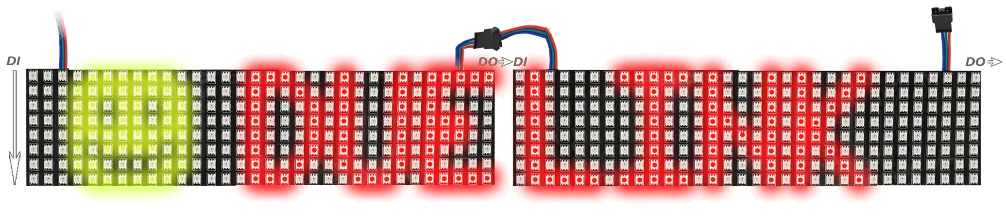
Things are quite different when using horizontal scanning as the system supports panels in different configurations. When connecting panels horizontally the panels need to be in order like the image below.
![]()
# 3 horizontal 16x16 panels creating 48x16 display
Dim a1[]={1,# Pin used
    16, # Individual panel width
    16, # Individual panel height
    0} # Horizontal scanning
    GfxCfg(3, a1, 48, 16, 1)# type 3, 48x16 leds, buffered x1

_x = 16*3

while 1
    Clear(0)
    Text("DUELink", 0x00FF00, _x, 0)
    Show()
    _x = _x - 1
    if _x < -20
        _x = 16*3
    end
    Wait(10)
wend
When connecting panels in a matrix, to build up larger "panels", they need to be connected as follows:
![]()
# 4 panels placed as 2x2, where each one is 16x16 pixels, creating 48x48 pixel displays
Dim a1[]= {1,# Pin used
    16, # Individual panel width
    16, # Individual panel height
    0} # Horizontal scanning
    GfxCfg(3, a1, 48, 48, 1)# type 3, 48x48 leds, buffered x1

_x = 6

while 1
    Clear(0)
    TextS("DUELink", 5, _x, 0, 1, 2)
    Show()
    _x = _x + 1
    if _x < -20
        _x = 6
    end
    Wait(100)
wend
It is also possible to connect panels vertically by simply ordering them exactly same as the matrix above, but only use the first left column.
## 3 vertical panels of 16x16 each creating 16x48 display
Dim a1[]={1,# Pin used
    16, # Individual panel width
    16, # Individual panel height
    0} # Horizontal scanning
    GfxCfg(3, a1, 16, 48, 1)# type 3, 16x48 leds, buffered x1

_x = 6

while 1
    Clear(0)
    TextS("DUELink", 5, _x, 0, 1, 2)
    Show()
    _x = _x + 1
    if _x < -20
        _x = 6
    end
    Wait(100)
wend
It is possible to make your own panels using LED strips. For example, 5 strips of 50 LEDs each can be used to make a 50x5 LED panel. The strips need to be connected in a zigzag pattern. This makes it easier to run the connections any way.
This is a partial image to demonstrate the connections.
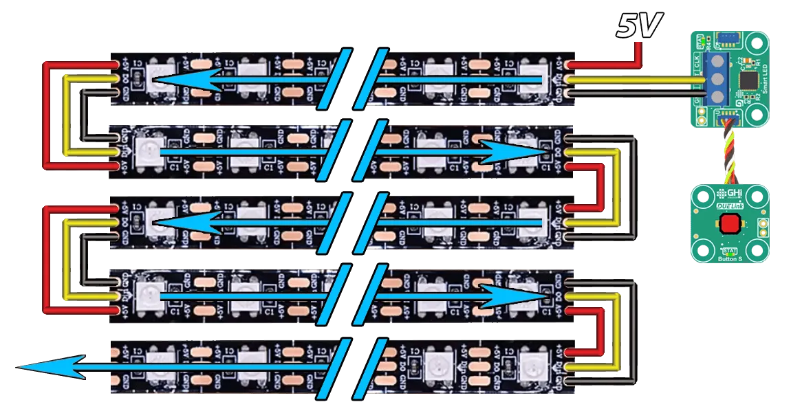
Dim a1[]={1, # Pin used
    50, # Individual panel width
    5, # Individual panel height
    0} # Horizontal scanning
    GfxCfg(3,a1,50,5, 1)# type 3, 50x5 leds, buffered x1

_x = 50

while 1
    Clear(0)
    TextT("DUELink", 5, _x, 0)
    Show()
    _x =_x + 1
    if _x < -20
        _x = 50
    end
    Wait(100)
wend
A single strip of NeoPixel LEDs is nothing but a panel with a single row. This example assumes a strip of 50 pixels.
Dim a1[]={1, #pin used
    50, #individual panel width
    1, #individual panel height
    0} # Horizontal scanning
    GfxCfg(3, a1, 50, 1, 1)

_x = 0

while 1
    Pixel(0x110011, _x, 0)
    Show()
    _x =_x + 1
    if _x > 50
        _x = 0
        Clear(0)
    end
wend
2Pin addressable LEDs can be used through SPI bus, but they are not supported by the graphics engine. See SmartLED for examples.
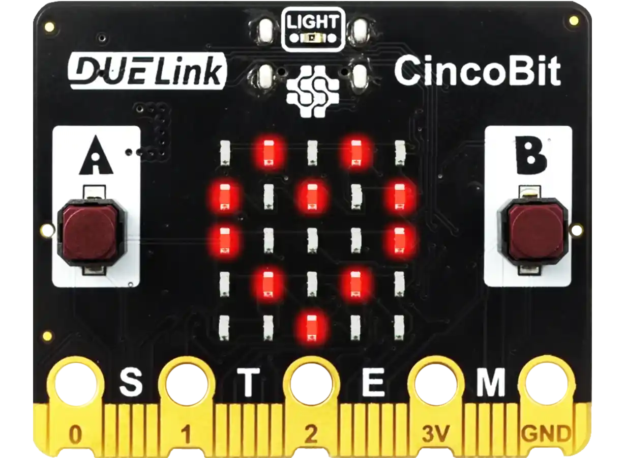
LED Matrix Scanner
This is a perfect match for CincoBit with its 5x5 LED matrix. This type supports buffered mode, with 1x multiplier only.
Dim a1[11] = {0,11,19,18,21,22,7,5,0,8,6} # first number sets common-anode, second 5 for data, third 5 for scan

GfxCfg(4, a1, 5, 5, 1)# type 4: 5x5 type, 1: buffered x1

while 1
    TextT("DUELink", 1, _x, 0)
    Show()
    _x= _x-1
    if _x < -40
        _x = 6
    end
    Wait(100)
    clear(0) # need to clear for next character
wend
The scanner also works great for other LED modules, such as LED S404 and others. The data are used to set the individual segments and the scanner pins sweep through the individual digits.
The LED driver helps in setting the right pixels to show the wanted digits.
Dim a1[13] = {1,1,2,3,4,5,6,7,8,9,10,11,12} # common pin, first 8 for data, second 4 for scan

GfxCfg(4, a1, 8, 4, 1)# type 4: 7seg (8 leds) x 4 digits, 1: buffered x1

# Show number 1 by turning on the right 2 LEDs on the first segment
Clear(0)
Pixel(1,2,0)
Pixel(1,1,0)
Show()
LED Matrix List
In this mode, the graphics engine scans and updates the LEDs one at a time. This mode works great with LED MT1208.
In this mode, an array contains a list of all LED pins. This is only supported in buffered mode, with x1 multiplier.
Dim a1[]={1,12,
    12,1,
    1,3,
    3,1,
    12,3,#5
    3,12,
    1,4,
    4,1,
    12,4,
    4,12,#10
    3,4,
    4,3,
    1,5,
    5,1,
    12,5,#15
    5,12,
    3,5,
    5,3,
    4,5,
    5,4,#20
    1,13,
    13,1,
    12,13,
    13,12, #24
    ## add the rest, to 96!

    }
    GfxCfg(5, a1, 12, 8, 1)# type 5, 12x8 leds, buffered x1

_x = 6
while 1
    Text("DUELink", 0xFFFFFF, _x, 0)
    Show()
    _x = _x + 1
    if _x < -20
        _x = 6
    end
    Wait(100)
wend
ePaper
These displays retain the graphics even after losing power. They are great for badges, labels and other zero-power usage. A good example is ePaper M29.
Note that ePaper displays need several seconds to update, which completely blocks the system and the module become unresponsive during the update.
Once updated, ePaper retains the content without the need for power!

loading...