Arduino

This is an interesting option because it allows a DUELink to be used in 2 very different ways. You can program any of the modules using the Arduino IDE/software. Or, you can use an Arduino board to control a chain of Daisylinked DUELink modules. We will cover them individually.
Modules Using Arduino IDE
The chip used on DUELink modules is STM32C071, which is fully supported by the Arduino IDE through the ST extension.
While you can do this on any module, we recommend using DueDuino for a first-class experience with Arduino and DUELink.
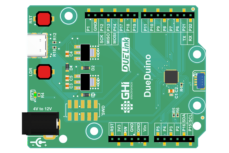
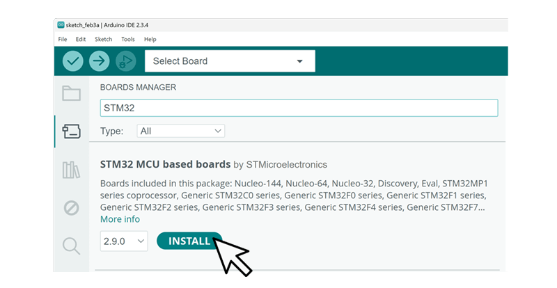
Start the Arduino IDE, and install the STM32 MCU based boards extension under Board Manager. More details are found here.
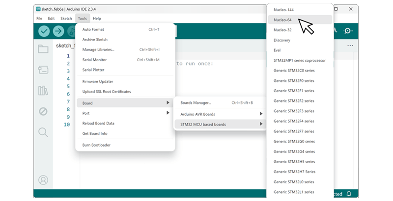
Under Tools/Board/STM32 MCU based boards: Select Nucleo-64.
Under Tools/Board part number: Select Nucleo C071RB.
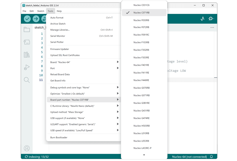
And finally under Tools/Upload method: Select STM32CubeProgrammer(DFU) for file upload.
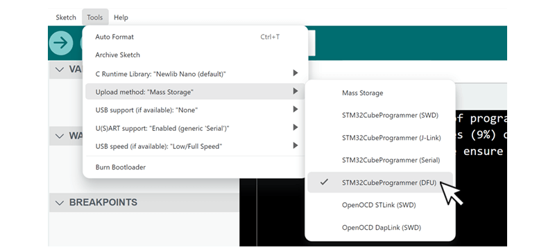
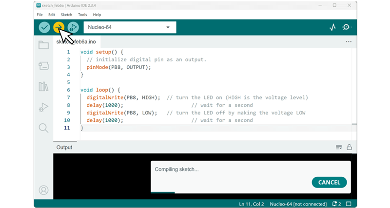
Add this code to blink the status LED, which is connected to pin PB8.
void setup() {
  // initialize digital pin as an output.
  pinMode(PB8, OUTPUT);
}

void loop() {
  digitalWrite(PB8, HIGH);  // turn the LED on (HIGH is the voltage level)
  delay(1000);                      // wait for a second
  digitalWrite(PB8, LOW);   // turn the LED off by making the voltage LOW
  delay(1000);                      // wait for a second
}
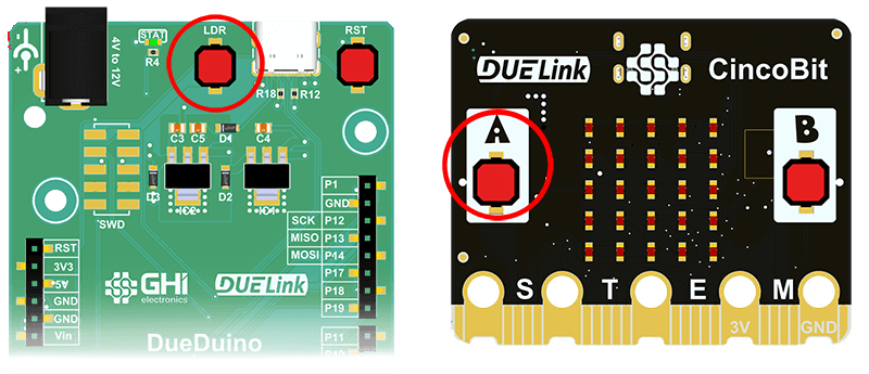
Put the board/chip in loader mode (DFU) by holding LDR or "A" buttons down while resetting the board.
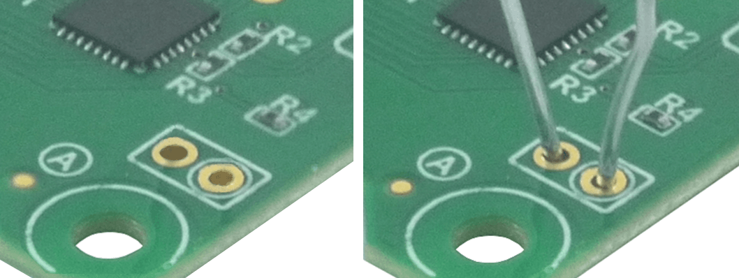
If no button is found, there are special 2-hole-pads with BOOT0/LDR and 3.3V found on the module. Use a paper clip (or a wire) to short the two pads.
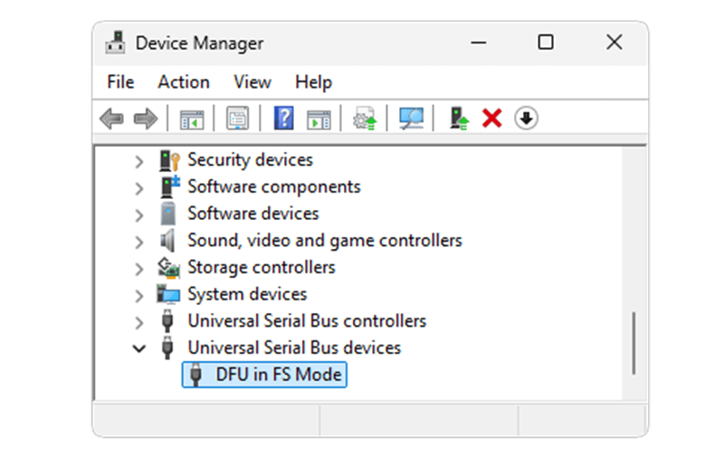
Reset the boards, and now it is in DFU mode. You can verify by checking the Device Manager.
You can now send the program from the Arduino IDE
If you'd like to go back to using DUELink software you'll need to reload its firmware. Details are found on the Loader page.
Arduino Daisylink
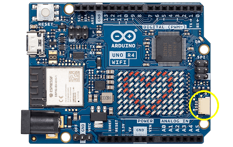
Any board running Arduino software can utilize DUELink modules. An example can be Arduino Uno R4 WiFi, which already include a JST connector.
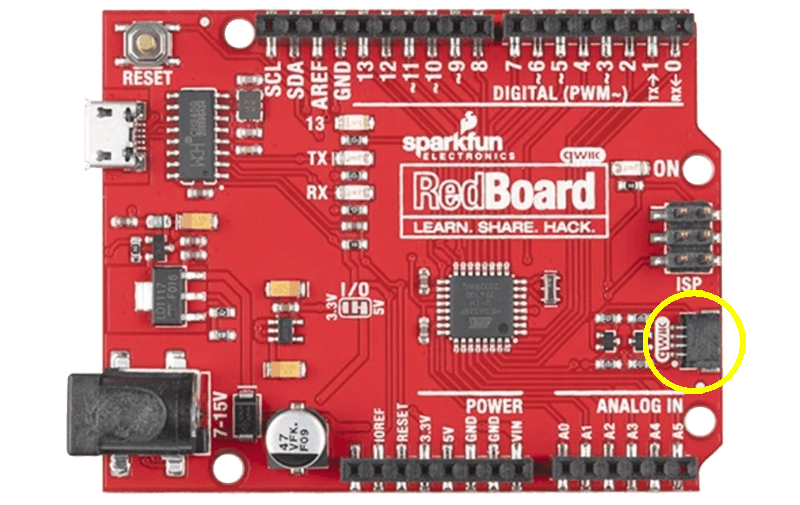
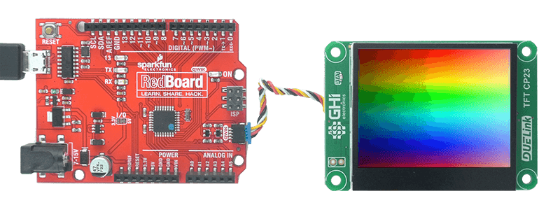
The Sparkfun Redboard Qwiic is another option.
We recommend using our DueDuino for a hybrid first-class experience with Arduino and DUELink.

You are now ready to access a chain of Daisylinked modules that are connected to the JST connector.
Boards without a JST connector can use the Breakout module to wire the connections.
Here is the Arduino Uno R4 WiFi connected to a 2.3" color display with capacitive touch screen.
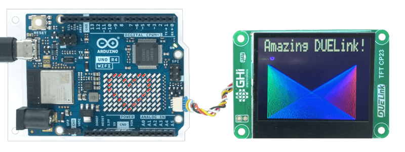
You can do the same using Sparkfun Redboard Qwiic.
Here is an example to blink the STAT LED.
#include <DUELink.h>
#include <DUELinkLib.h>
DUELink due;
TwoWireTransport transport(Wire1);

void setup() {
  // get ready, over I2C
  Wire1.begin();
  due.begin(transport);

  //blink LED
  due.statled(200,200,50);
}